 Skip to main content

FAQs
FAQ's for Triangle Tube
how to browse faqs by topicFAQ's for PS Boilers
- High Flue temperature
- High Delta T between flue temp and return water temp (Typically 25-30˚F)
- Condensate trap fluid color/condition (esp. if black)
- Ignition issues, (hard/delayed ignitions)
- Increased fuel consumption
- High CO values, poor combustion performance, combustion performance has
- changed
- Discolored / Distorted venting materials
- Dirty combustion air i.e.: farm, dairy, Road debris, Salt air
- CO detector alarms
- Igniter rusty
- Warped / discolored burner plate
- Corrosion/discolored heat exchanger
- Burner plate gasket white in lieu of Red/Orange
- Insulation (refractory) or debris on tube sheet-observed through sight glass
- Time... How many years has it been?
E-14 is a disturbance on the low voltage side of the system. This is separated into two parts.
1) The unit resets and begins to work. E 14 returns in an un-predictable time frame.
2) Does the unit reset, but goes to E 14 with-in 5 seconds.
1) This often is caused by the dry contact in the aqua-stat in the domestic water heater. The dry contact water heater’s aqua-stat should be replaced with a PSRKIT-22 Triangle Tube IDHS. This will now allow the boiler to see the actual temperature in the tank and determining when to go into water heating operation.
2) This disturbance is far more difficult to pinpoint. It is important to be sure that the reset is working. When the reset button is pressed and released, the E-14 should disappear, and a software code show up, once that clears, the E-14 will re-appear we now know the reset works. Remove the entire field wires connected to terminals 7 through 19. Try to reset the boiler. If the E14 goes away, one by one re-install the field to see what field device is affecting the boiler. Remove the X04 plug from the MCBA module. (This is the plug with 2 blue wires and 1 yellow wire. Be sure to look carefully how the plug is connected and when re-connecting it, be sure to put it back the same way you removed it.) Reset the boiler, if the E-14 goes away and is replaced with a b-40 and a 9-## reconnect the X04, if it immediately goes to E14. We now have isolated the fault.
Since the E14 stopped when the X04 was removed and now is back in place. Remove the 2 yellow wires from the flue sensor, reset the boiler. If the b-40 and 9## returns, replace the flue sensor. If the E-14 comes right back, replace the wires on the flue sensor, then remove the wires in the top of terminals 17 and 18 (one has a blue and a yellow wire in it, the other has a single blue) let them hang in the air, reset the boiler. If the fault clears, isolate and insulate each of the wires. They are not being used, so they may remain isolated and insulated
If the E-14 does not disappear when the X04 is removed remove the X05 plug. Then reset the boiler, if the boiler resets and shows the b40 and the 9##, then replace the X04, reset the boiler and operation should commence. This is an indication that there is a problem with the outdoor sensor or the wire for the outdoor sensor.
The following items should be checked:
- Verify that the boiler and heating system are filled with water.
- Ensure the boiler and heating system have been properly purged and there is no air trapped in the top of the heat exchanger.
- Inspect and verify heating system piping and its components.
- Ensure piping is per the recommendations given in the Installation Manual or other approved design.
- Use a temperature-sensing device to measure the supply water temperature leaving the boiler. Compare this measured temperature the display temperature (INFO Mode, Step “1” Shows the supply temp.)
- Replace the supply temperature sensor if the temperature comparison is largely varied by more than 10ºF.
- Be sure that the boiler circulating pump is operating, has voltage and is moving water. Check fuses to insure they are intact. Check all controls to determine that they are calling for the pumps to be operating.
1) Remove and inspect the igniter. Igniters are consumable. After many ignitions and or subjection to high temperatures, it may be recommended to replace the igniter when you have failed ignition issues.
2) Check the connections of the igniter wire, be sure they are strong connections and that the wire is not in contact with any metal surface.
3) Remove the air intake pipe from the burner, inspect the venturi, feel the inside rim of the air inlet hole, it should be pristine, tight in the shroud, no holes, no breaks, no cracks. A large amount of black residue inside the venture would indicate the venturi has started too broken down and needs to be replaced.
4) With the gas valve turned off, check the incoming gas pressure on the gas valve of the unit. N.G should have approximately 6 to 7 inches and L.P should be approximately 11 inches. When the gas valve opens for ignition, the pressure is not allowed to deviate more than one inch W.C..
5) A final test if we cannot create fire, attach the manometer to the outlet port of the gas valve. During the pre-purge you must develop 1.5 to 2 inches W.C. at a minimum to pull gas through the gas valve. If we are not developing the correct negative pressure, the system may be blocked in the combustion area or exhaust lines, or the blower is not developing the correct amount of airflow.
1) Remove the igniter and reset the controller. If the fault will not reset, then unplug the gas valve and reset again. If the unit will not reset, replace the control module. Be sure to test the resistance of the gas valve, these are 120 volt gas valves and should have approximately 375 ohm resistance on one coil, and 717 ohms on a second coil.
2) If the controller resets, replace the igniter and also replace the insulation block. There will be an alignment tool, be sure to use to install the insulation block.
The boiler display will indicate a status code of 5 during the ignition sequence for 4 minutes before locking out.
- Disconnect the connector at the blower. Restart the boiler sequence and check for 35Vdc at the connector between the black and white wires (pin 1& 5).
- If 35Vdc is not present at the connector, inspect the wiring harness and replace if necessary. Replace the control module if wire harness replacement does not resolve the problem.
- If 35Vdc is present at the connector, reconnect the wire harness to the blower and ensure a secure connection. If problem is not resolved, contact Triangle Tube Technical Support for additional assistance.
When the unit is heating, it is important that the supply sensor is higher than the return and the flue, the flue is lower than the supply and higher than the return, and the return should be the lowest. Once the burner is off, the flue should become lower than the return. A true short in either coil of the gas valve will also give the e44, but will not reset under any condition, and is many times fatal to the MCBA. This will require an ohm check of the gas valve coil. The gas valve should have a 32 ohm reading on coil 1 and 18 ohms on the second coil. The rectifier head on the gas valve may also be shorted, requiring all three parts (gas valve, rectifier head, and MCBA) to be replaced.
FAQ's for PA Boilers
- High Flue temperature
- High Delta T between flue temp and return water temp (Typically 25-30˚F)
- Condensate trap fluid color/condition (esp. if black)
- Ignition issues, (hard/delayed ignitions)
- Increased fuel consumption
- High CO values, poor combustion performance, combustion performance has changed
- Discolored / Distorted venting materials
- Dirty combustion air i.e.: farm, dairy, Road debris, Salt air
- CO detector alarms
- Igniter rusty
- Warped / discolored burner plate
- Corrosion/discolored heat exchanger
- Burner plate gasket white in lieu of Red/Orange
- Insulation (refractory) or debris on tube sheet-observed through sight glass
- Time... How many years has it been?

Tank-in-Tank Technology
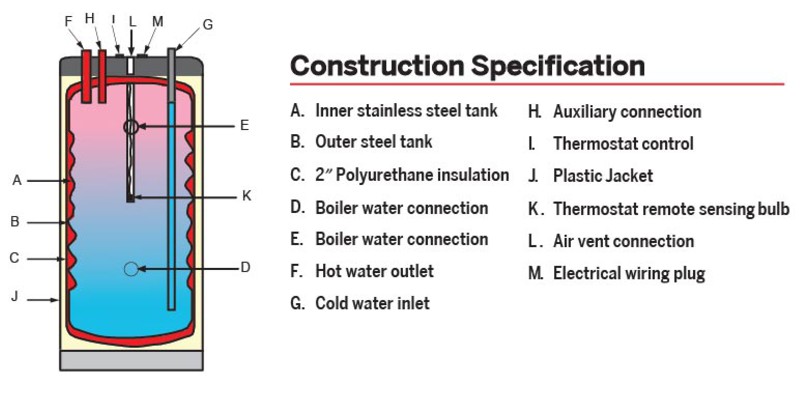
- High Efficiency Hot Water: Thanks to the exceptionally large heating surface area (typically 1.5 to 2.5 times greater than a coil), Tank-in-Tank systems can use the whole heating power of the boiler. Consequently the Tank-in-Tank can heat a large quantity of domestic hot water in an exceptionally short time. As a result of this rapid heating capacity, the volume of stored water can be reduced and energy loss kept to a minimum. Furthermore, condensing boilers benefit from being able to work in condensing mode for much longer, giving much greater fuel efficiency.
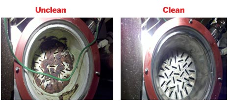
- Self-Descaling: The tank is free to expand and contract as a result of the variations in pressure which occur with every hot water draw-off. The corrugations amplify these movements and prevent the formation of lime scale on the surface of the exchanger,which retains its high performance throughout its service life. The Tank-in-Tank requires no anode protection and the self-descaling feature eliminates the need for regular descaling. A primary coil is not required and there is no need to worry about contamination, leaking and sludging caused by cracked linings.
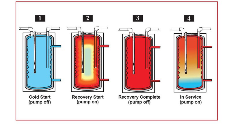
- Anti-Legionellae: Natural turbulence across the concave base keeps particles in suspension, preventing formation of sediment and - aided by consistently high store temperatures (above 140 F) - helps to avoid growth of legionellae bacteria. In a tank with a coil, the water at the bottom remains tepid; so the legionellae can survive and multiply.
FAQ's for PT Boiler
- High Flue temperature
- High Delta T between flue temp and return water temp (Typically 25-30˚F)
- Condensate trap fluid color/condition (esp. if black)
- Ignition issues, (hard/delayed ignitions)
- Increased fuel consumption
- High CO values, poor combustion performance, combustion performance has changed
- Discolored / Distorted venting materials
- Dirty combustion air i.e.: farm, dairy, Road debris, Salt air
- CO detector alarms
- Igniter rusty
- Warped / discolored burner plate
- Corrosion/discolored heat exchanger
- Burner plate gasket white in lieu of Red/Orange
- Insulation (refractory) or debris on tube sheet-observed through sight glass
- Time... How many years has it been?
Normal reason for the drift is a lack of flow through the heat exchanger; either the pump is undersized, restricted, or there's a small air pocket in the top of the heat exchanger. Check for power to the pump, be sure the pump is running, and check the piping for a restriction in the system. Look in the alarm history and see what process the boiler was in when the lockout occurred. See if the flow is halted before the post pump operation has occurred.
To remove from hard lockout; take a metal object and short out the first set on pins on the left hand side, top to bottom for two seconds.
1) Remove all field control wiring. Attempt a reset, if the fault ends, find the problem in the external controls.
2) With the removed field wiring removed if the error remains, remove the X06, the X03 and the nX07 from the boiler in question. Reset the control. If the boiler resets, then we need to know which plug is giving us the fault. At this point contact tech support.
3) With the X06, X07, X03 removed, the fault will not reset, and then replace the control module. If this is part of a cascade system contact Tech Support before you proceed.
2) The request for an installer access code will be prompted, this access code is “054”. Use the left and right keys to move the cursor and the up and down to change the digit,
3) Once "054" is entered, you be in the advanced parameters. Use the boiler manual or the Tri-Max control supplement to change the actions.
2) Be sure that all of the settings in the controller are correct. Refer to the correct manual for setting instructions.
3) Be sure that there is a completely filled tank and boiler heat exchanger is free of air.
4) Remove the actuator head off the diverting valve inside the boiler cabinet. Be sure that the spring has driven the cage completely to the top of the valve. If it is not completely at the top, grab the stem with pliers and apply a small amount of force to get the valve to seat. If the cage moves and seats, rebuild the valve and chemically clean the heating system.
5) Using a 5 Gal. bucket marked 2/3 of the way to the top. With the tank cold, go to the largest tap in the home (normally the bath tub) and open it full. Then close the cold water feed to the water heater to a point that it takes the fixture 1 min to fill the bucket from empty to the mark. This will insure we are not moving more than 3GPM through the water heater.
6) All A.S.S.E. mixing valves will fail to the cold side. If the tank is hot and the outlet of the valve cold, the mixing valve is either fouled or stuck, either way you have to replace the valve.
- Start the boiler and set the boiler into HIGH fire.
- Press the round INSTALLER button. Enter the access code “054” press OK. Press the RIGHT button to highlight the Manual Operation icon, press OK. Press the OK button while the FAN icon is highlighted to manually fire the system. Press the RIGHT button and move the slide to 100%.
- Remove the cap in the exhaust flue pipe; install the probe of the analyzer into the exhaust flue pipe hole in the flue pipe.
- If the O2 reading is above 3.9% turn throttle screw CCW to lower the O2, if the reading is below 3.9% turn the throttle CW to increase the O2. Set the boiler into LOW fire. If you are still in high fire just press the LEFT button and move the slide to 1%.
- Check the O2 reading in low fire, it should not differ more then 2/10 of a percent.
- If the readings between High and LOW fire differ more then 2/10 %, call Triangle Tube Tech Support.
FAQ's for Challenger
The test procedure is as follows; all these tests need to be done with the #1 in the right window. Test the controllers output. There should be 26+ volts DC between the black and white wires. If the 4 wire plug are disconnected, there will not be an output to the 120 volt plug. With the 4 wire plug connected, and the #1 in the right window there should be 120 volts AC to the three wire plug to the blower. If either of these conditions is not present, replace the controller. Short of that, it is the blower that will have to be replaced. Be sure to remove all of the parts from the old blower and install them in the new blower. (IE: Gas pipe, Venture, retaining clip, exhaust gasket, and restrictor ring.
Remove water from boiler. Remove LWCO; on the WET side of the LWCO (the part that is in the water) inside the ¼ inch opening there is a small weep hole. The weep hole is about the size of an 18 gauge wire. Find and clean out the weep hole and re-install the LWCO. Fill the boiler with water and restart the system. If this does not correct, replace the LWCO. Side bar NOTE; the system may need to be cleaned or an inhibitor may be needed to be added. See BOILER COMMISSIONING
1) If we are producing fire but not proving, this is a condition of lacking ground or a defective flame signal.
The unit MUST have a dedicated power supply from the incoming distribution electrical panel, with a full sized uninterrupted ground.
Be sure to remove the igniter and clean it. If more than 2 years old it would be prudent to replace it. Also check the condition of the orange ignition wire, make sure it has good connections on both the igniter and the ignition transformer. Insure that the wire is not touching any metal.
The flame signal is determined by the ignition transformer. Since we cannot establish a flame, we cannot read the flame signal; therefore check the ignition transformer once again being sure of the condition of the connector on the wires.
2) If we are not producing any flame, then we are missing one of the three ingreedences needed for fire. Ignition, Fuel, and Oxygen.
We will attach our manometer to the inlet port on the gas valve; we should have Approxitmilly 6” of pressure for Nat. gas, Approxitmilly 11” for L.P.
We should be able to see the spark generated when the unit goes into ignition through the inspection mirror attached to the left side of the heat exchanger. It is normally very visible.
Removing the exhaust pipe from the condensate pan to increase the airflow from the blower. If we ignite then, we are restricted either in the exhaust pipe, or in the heat exchanger. Examine the exhaust pipe and remove the plate from the aluminum block and examine the flue ways for cleanliness.
During the testing with the exhaust pipe there should be a strong order of gas coming from the outlet, if not, with the unit re-assembled, place your manometer on the outlet port of the gas valve. During pre-purge there should be a ½ inch of negative pressure developed. When the ignition cycle begins, the negative pressure should disappear, if it does not it is a defective gas valve.
3) If the unit lights, proves but when the blower begins to slow, the burner goes out. There we have a combustion issue that will require the use of the combustion analyzer. Make sure that at a forced high fire, we have an O2 level of 4.3% and when forced to low fire does not change more than 0.2%.
Find My Product’s Serial Number


General FAQ's

Triangle Tube designs and manufactures industry leading hydronic heating solutions, including high efficiency boilers, domestic water heaters, heat exchangers, and controls. These products can provide years of service when properly installed. Our commitment to this performance is demonstrated not only in the attention to detail in our engineering and manufacturing, but also in the hundreds of hours of training that we provide our representatives, wholesalers, and installers every year. In addition, we provide technical support to our authorized installers through our Corporate Engineering team, who average over 20 years of experience in the hydronics industry.
We have developed a team of authorized representatives and wholesalers that will provide installers and consumers with the quality product and service that will ensure maximum performance. Triangle Tube stands behind our products through our warranty policy. However, we cannot provide this warranty protection if our products are not purchased through our authorized representatives and wholesalers. Unauthorized sellers (online or otherwise), may be selling discontinued or refurbished models, and cannot visit your home to ensure properly sized and installed equipment. Most online sellers cannot supply references in your neighborhood, and, since they do not perform the installation, will deny responsibility for any problems.
By selecting an authorized representative, wholesaler, or installer you will receive:
A responsible, professional installer with years of good experience that you can verify, and who isclose to home.
A contractor with a solid business who visits your home before they quote a price and who willstand behind the product after they get paid.
A contractor that has been trained by Triangle Tube on the product so that they will install itaccording to specifications.
Therefore, it is the policy of Triangle Tube to provide technical support only to licensed heating technicians installing product supplied by authorized dealers. Triangle Tube will NOT provide technical support for product supplied by unauthorized dealers.
It is also the policy of Triangle Tube to provide a warranty only to product sold by an authorized dealer and installed by a licensed heating technician. Triangle Tube will NOT provide a warranty for our product that is purchased online or through other unauthorized channels, and/or installed by someone other than a licensed heating technician.
